
World is in constant progress. Paraglider design is no different. Accumulating years of experience we arrived at a number of proven solutions…
@paraelement

NFC - Near Field Communication chip
copy link
The paraglider has a chip installed under the wing sticker, thanks to which you will get immediate access to our system with an NFC-enabled phone.
You will find there all data of your paraglider model, warranty conditions, user manuals, current documentation and service notes, and you will also be able to use the function of notifying about the loss, theft or finding of equipment of another owner.

DRA - Dudek Reflex Airfoil
copy link
DRA – Dudek Reflex Airfoil -applied in PPG wings fully autostabilised arofoil, based on long years of research and experience. In our variant we managed to get rid of typical flaws associated with these aerofoils.
Simply put, it is an aerofoil which – in case of decreased angle of attack – automatically tends to have it increased again. In other words, it always stays in neutral position regarding its load. On drawings it’s an aerofoil that has its tail turned upwards 🙂

DOA - Dudek Optimized Airfoil
copy link
Dudek Optimized Airfoil It incorporates all our experiences stemming form previous designs and as a special feature is optimized with dedicated engineering software.

P&R - Push & Relax Technology
copy link
Push&Relax technology – PPG canopies marked with this symbol demonstrate exceptionally stable flight on full speed bar, that is at high speeds.
Why stability at high speeds is so important?
In free-flying speedbar is used time to time, most often as a radical measure to escape from sink area or as a defence against being blown back into lee. Still, there are many pilots who do not use speed bar at all. That’s why designers so far paid little attention to paragliders stability in such configuration. On the contrary, in PPG flying a speed bar is used commonly. It is only a pilot who decides the route, not the thermals location or terrain characteristics. It is nothing uncommon when a pilot takes off, opens the trimmers, engages speed system and gets on an umpty kilometers route. In such case lack of stability and comfort would be really distressing.
How does lack of stability manifest itself?
Good stability of your canopy can be compared to proper balancing wheels in your car. When you drive slowly, this is not much of a problem, but the faster you drive the more evident vibration you get. Badly stabilized canopy will move accordion-style, quiver and resonate, causing pilot to be afraid of using speed system (and rightly so).
Why the canopy becomes unstable?
It’s really all about balancing – a canopy can be trusted when the tensions run evenly all along its surface. While great majority of designers take pains to make sure their paragliders are evenly tensioned at trim speed, they are neglecting stability at max speed. That’s a big mistake since increased ram effect, air pressure inside the wing and increased lift in individual areas can drastically alter distribution of loads and tensions. If it was not taken into account, the paraglider will quiver and behave accordion-wise.
How did we succeed in effective stabilising the canopy?
Push&Relax Technology is centered around fully reflex aerofoil. Basically that’s why it is tuck-resistant and self stabilizing in all directions. Still, just using the reflex aerofoil is not enough. Structure of inner reinforcements, precise shape of individual surface panels tensioning all aerodynamical surfaces together with leading and trailing edges have to be carefully combined, so that canopy will remain properly tensioned not only at 40 km/h, but also at 60. In order to succeed you have to include research, a lot of trials, sophisticated software and first of all huge practical experience.
We did all of that and even more. In effect when flying Dudek paragliders marked with Push&Relax Technology sign you can safely put the pedal to the metal and enjoy fast flight.

CSG - Canopy Shape Guard
copy link
Na CSG składa się szereg podsystemów:
CSG consists of a number of lesser systems:
- VS (V-shaped Supports) – they are there to ensure upper surface smoothness, exact aerofoil reproduction on entire wing span, better load distribution and possible small number of suspension points.
- RSS (Reinforcing Strap System) – an independent reinforcements net on lower surface, strengthening and stiffening all construction.
- OCD (Optimized Crossports Design) – the intercellar openings have carefully designed shapes and are optimally placed between stress lines in the ribs, in order to ensure efficient pressure distribution in the canopy and its quick inflation.
- CCS (Closed Dell Structure) – this is a number of closed cells in most important locations. It?s goal is to hinder the backflow from the cells out and thus to facilitate their refilling and canopy recovery in case of a collapse.
Canopy Shape Guard effectively stiffens the wing along all its span, practically eliminating any lateral canopy work. Its only flaw are the increases in weight (about 1 kg), material- and labour consumption, and of course in overall costs. Yet it is well worth the sweat, as in turn we get a no-compromise product of highest performance and quality, that above all is able to keep its planned parameters for a long, long time.
Not every wing features all DRA subsystems – you will find details in each wing description.

APC - Auto Pitch Control
copy link
Auto Pitch Control – the wing stays over your head without pilot control (during launch and flight).

LR - Laser Technology
copy link
Capabilities of the laser cutter allow for serial cutting of complicated shape narrow elements in large numbers, their optimal placing in relation to structure of the textile and highest possible precision of cut.


Used solutions

CP - Catch Pins
copy link
Loops sewn to the upper surface of the canopy on the leading edge allow it to be attached to the ground with the pins supplied, in order to fix the canopy in place when launching on steep slopes or snow.

AIV - Air Inlets Valves
copy link
The system consists of special valves on the inlets of the canopy, faithfully reproducing their shape. The valves remain open to incoming air during take-off and standard flight and close to the air flowing out of the canopy. By maintaining high internal pressure, it helps to obtain the right energy for smooth infinity tumbling.

LE3D - Leading Edge 3D
copy link
The LE3D uses a system of additional cuts on the top surface of the leading edge along the wing chord. The upper surface of each cell in these areas consists now of three elements instead of one.
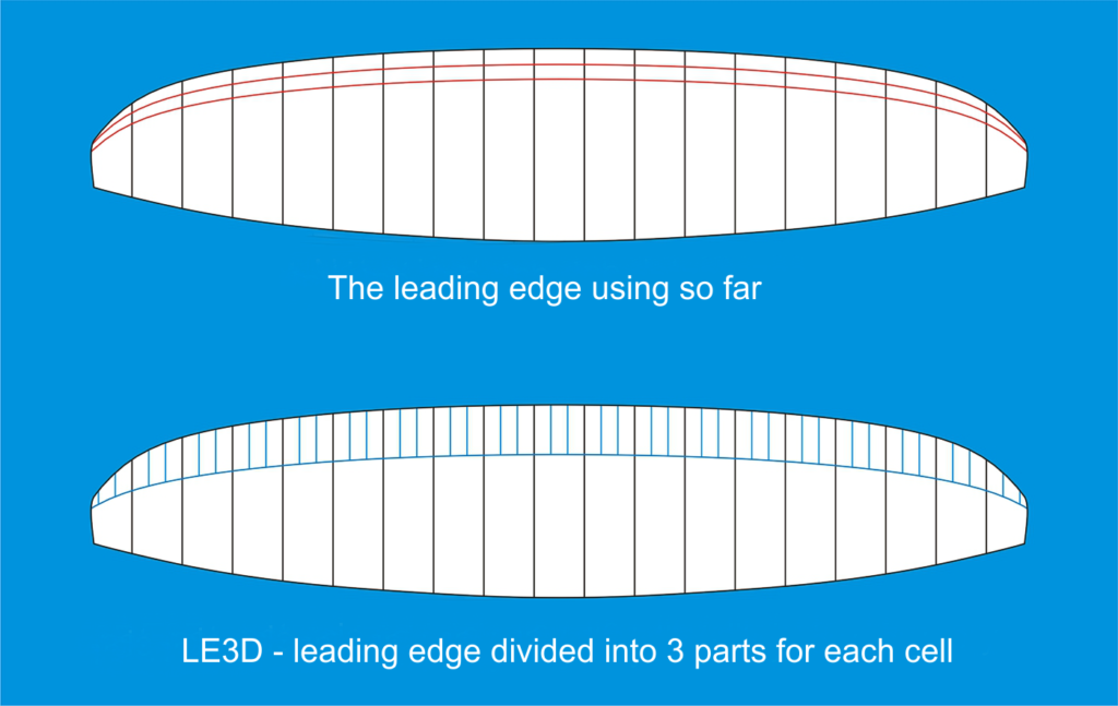
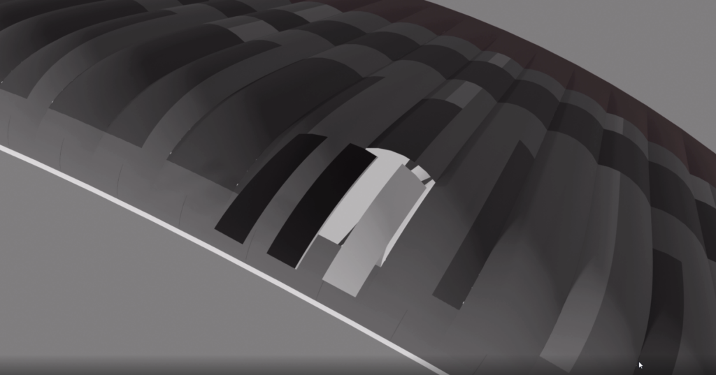
Additional cuts minimize fabric wrinkling and more accurately reflect the designed shape of the aerodynamic profile in the crucial zones, where most lift is generated.
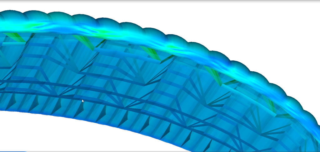
We have been working on the scope and shape of LE3D for over a year, first by analyzing the results of computer simulations of air flows (outstanding work by Jacques Peugeot), and then measuring the performance of the prototypes. As observed, implementation of this solution in our latest designs has positively influenced the glide ratio of the wings.

FET - Flexi Edge Technology
copy link
The leading edge is closed to the airflow, and its precise shape is kept with laminated cloth reinforcements, incorporating synthetic rods. The rods make the leading edge stiffer and smoother, bringing improvements in many areas – from easier inflation, through stiffening the canopy in flight to improved general airflow.
Another advantage is possibility of using three rows of suspension lines instead of four, thus decreasing parasitic drag and distinctly improving overall performance.
Application of flexible synthetic rods was tried for the first time in the Hadron. Then, positive experience led us to use this technology in many other designs of various classes.

SN - Shark-nose
copy link
Airtakes designed and executed in Shark-nose technology meaning specific, concave shape of the reinforced profile area at its leading edge (the name comes form the very shape, reminding shark’s nose).
Due to such shape the intakes can be smaller and moved a bit back, so that leading edge remains undisturbed and offers smooth airflow. The internal pressure of the canopy stays stable within wide speed range. In everyday flying this results in greater resistance to stalls (e.g. when thermalling) and front collapses at high speeds.

LE2R - Leading Edge Double Reinforcements
copy link
Leading Edge Double Reinforcements are additional reinforcements between the cells, which stiffen the leading edge and keep the profile ‘clean’ during the flight at full speed.

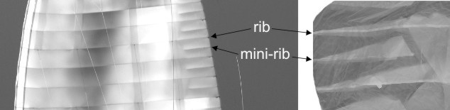
MR - Mini-Ribs
copy link
Mini ribs speak for themselves – they are additionally introduced in the trailing edge between main ribs. Their task is to decrease ballooning (expanding and deformation of the cells) in this vital area af the aerofoil.
Keeping the rear part in shape reduces the drag induced behind trailing edge, thus improving general airflow and increasing airspeed.

HSS - High Speed System
copy link
High Speed System – to achieve good speed in flight, while maintaining safety and good landing parameters (flare).

3-1 - 3 to1 Pannel
copy link
3 to1 Pannel: partially integrated panels for weight optimization and better landing.

FT - Front Tube
copy link
Front Tube: leading edge inflatable: to support higher speed.

DBS - D Brake System
copy link
D Brake System: for a better flare during the landing.

ACS - Auto Cleaning Slots
copy link
Dedicated slots automatically removing dirt from the wing tips.


2L - Two-Liner
copy link
Two rows of lines. This solution is used in high-performance wings to minimize air resistance.

3L - Three-liner
copy link
Thanks to introduction of stiffening rods (Flexi Edge Technology) and other internal reinforcements, elimination of one suspension row – from four to three – was possible. In effect, reduced total length of lines led to reduction of the drag, thus improving overall performance of the design

CS - Cleaning Slots
copy link
Located at the wing tips make removal of dirt a way easier.
Risers functionality

TR - Trimmers
copy link
Straps are finished with loops for easier operation.

SS - Speed System
copy link
A system of lines and pulleys sewn to the appropriate straps, connected to the bar hanging under the harness. It enables smooth adjustment of the angle of attack during the flight.

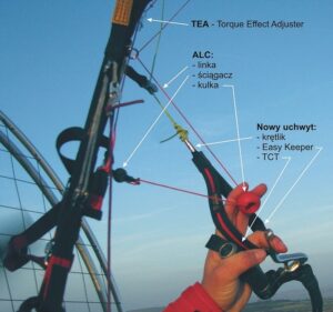
ALC Plus - Alternative Steering System +
copy link
New version of the Alternative Steering System ALC+ does not require adjusting it to actual suspension height. Prior to launch, the ALC+ handle is fixed to the risers with magnetic clip, keeping it in place and not tangled with the rigging. In flight the handle stays within easy reach, while elastic cord attached to its lower part prevents it from getting in propeller’s way and offers adjustment of the ALC+ line length to the present configuration of trimmers and speed system. This solution is practically identical to the original ALC ball, with the only difference that the handle can be fixed to the risers and it does not require any adjustment.
ALC+ allows for aggressive turns even at full speed without excessive alteration of the reflex airofoil. It is especially important in case of bigger canopies, inherently haunted by significant steering forces and low agility. When necessary, only the main steering handle can be used, with the ALC+ system ignored (rendering it inactive).


ALC - Alternative Steering System
copy link
The new system is based on a solution developed by Michel Carnet on his ReAction since 2007, at the World Championship in China.
ALC allows for aggressive, yet effortless, turns on full speed without influencing its reflex aerofoil. It is especially important in the case of bigger canopies, inherently haunted by significant steering forces and low agility.
The new steering component is a red ball, easily positioned to fit various harness hang-points and personal preferences. In addition, the ALC ball and line are routed in such a way to be easy to use without the risk of entanglement with risers or other parts. Of course you can use just the standard brakes if you wish, ignoring the ALC ball.

TST - Tip Steering Toggles
copy link
Our original idea, featuring additional miniature handles that steer the stabilizers. It is a great improvement on long flights, when opened trimmers and full speedbar make steering much harder.
Prior to grabbing miniature TST-handles (Tip Steering Toggles) pilot places the main steering handles in a special Toggle Docking Stations, equipped with strong neodymium magnets. In this way you can comfortably steer the wing via TST handles, not worrying about the brakes getting tangled.

TCL - Tip Control Line
copy link
TCL (Tip Control Line) allows you to make corrections and turns even at full speed, without too much interference with the reflex profile.
The steering element is a separate red line attached to the appropriate steering line leading to the tip of the stabilizer.

TEA - Torque Effect Adjuster
copy link
The task of this feature is to counteract the effect of engine torque, that tends to make the paraglider turn in the direction opposite to the propeller’s rotation. TEA balances the torque by adjusting the length of some wingtip lines, and it can be adjusted to match you specific combination of paramotor/propeller. Simple to use, effective and easy to toggle on & off in the air.
We also use automatic TEA: It works automatically after the line is installed on the appropriate side, depending on the direction of the twisting moment of the engine.

PA- Power Attack System
copy link
The PA (also known as Paap Kolar system) merges speed system with trimmer operation. It is devised only for competitors, understanding its effects and all difficulties involved. Regular pilots will need up to three months before fully mastering its use.
The general idea is simple: pressing the speedbar simultaneously releases the trimmers (and vice versa, releasing speedbar closes the trimmers ).
The system is sometimes supplied subject to personal agreement of our designer.

2D - Steering System
copy link
2D system is generally similar to the classic one – pilot has but two main steering handles to steer. However, it’s operation is significantly different. Due to division of main steering lines (there are two for each side now, with one of them going outside of the pulley), an experienced pilot can modify steering progression according to his own preferences.
The rigging scheme was designed for low progression in low and middle speed ranges, so that pilot has better control of the wing. At high speeds (trimmers released and speed system engaged) only the outer steering lines or special systems (TEA/TST) should be used.

BEA - Brake Elastic Attachment
copy link
Brake Elastic Attachment – elastic element fastening the handles to straps/lines (instead of magnets).

ELR - Easy Launch Riser
copy link
Split ‘A’ riser makes for easier launch and ‘big ears’
As in all other elements of the wing, the risers too must be constantly adjusted to the ever-increasing needs of the pilots. As a standard, every Dudek wing is equipped with a split A riser. Most of the lines go to the main riser, and the additional one has just one or two outer lines.
There are two advantages such a solution. Firstly, the big ears are a lot easier to introduce – you no longer have to reach high above the quick-links, and the taut lines do not hurt your fingers. Secondly, a start is much easier, too. With a dynamic push every wing has a tendency to form a horseshoe, i.e. to inflate the tips faster than the centre. The pilot can reduce this effect by grabbing only the main A risers, leaving the outer part hanging. The leading edge will then be pulled only in the central part and the tendency for the tips to speed up will be eliminated.
When the wing is in the air, you can recognise the risers without hesitation. But when the wing is lying on the ground it can be difficult, especially while preparing for a reverse launch and the risers just form a twisted bundle. That’s why we have distinctly marked the main A risers with yellow tape, so it is easier for you to find the correct risers and your instructor can instantly see if you are right.

ACC - Active Control C
copy link
Control of the wing with rear risers during accelerated flight.

EK - Easy Keeper
copy link
Indigenous way to hold the brake handles at the risers that keeps them firmly in place, while both attaching and releasing goes smoothly and easily. Used in most of our handles (TCT, ACT, SCT).

SL - Smart Lock
copy link
This solution allows for quick attachment of steering handles to risers. Fastening is done by putting the magnetic element of the holder to the slot mounted on the tapes. This is done easily and in any position of the handle. On the other hand, the handle is detached only by pulling it down.

NP - Napy
copy link
Metal clasps for attaching the brakes to the risers.

BEH - Big Ears Handle
copy link
Additional handles for easy tucking big ears, equipped with magnets and offering easy blocking the excess of line in a cleat. This allows you to keep the ears pulled in all the time, while retaining full freedom of brake operation.

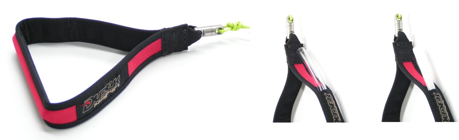
TCT - Triple Comfort Toggle
copy link
An easy conversion from hard through medium to soft brake handles. Equippped with a swivel adn Easy Keeper.
Available standard (bigger) and short (smaller) versions.

SCT - Sport Comfort Toggle
copy link
Sporty, soft and comfortable steering handles. Made of soft neoprene they fit you palm, while a red ball makes steering easier.
Equippped with a swivel adn Easy Keeper.
Competition pilots like them a lot.
Available standard (bigger) and short (smaller) versions.


ACT - Adjustable Comfort Toggle
copy link
Steering handles with adjustable loop size. Finished with soft neoprene, equippped with a swivel adn Easy Keeper. Apart from basic version there is enhanced one too, with a ball for easier steering andor loop to fix elastic band. Especially acro flyers and speed riders praise this solution.


DCT - Double Comfort Toggle
copy link
Makes possible to have your brake handles as you like them, in stiff or soft configuration. Used in older models of wings.